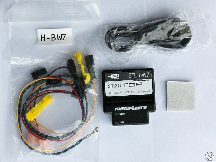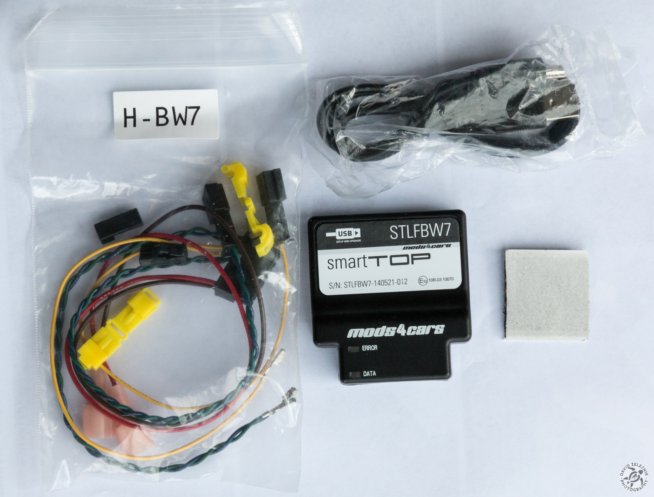
1 Box contents of the smartTop controller for the E85/86 Z4, from L-R: wiring harness and t-tap connectors, the controller module, USB cable, and self-adhesive velcro pad for mounting the controller. These are the installation steps that I followed, the full install manual can be found here.
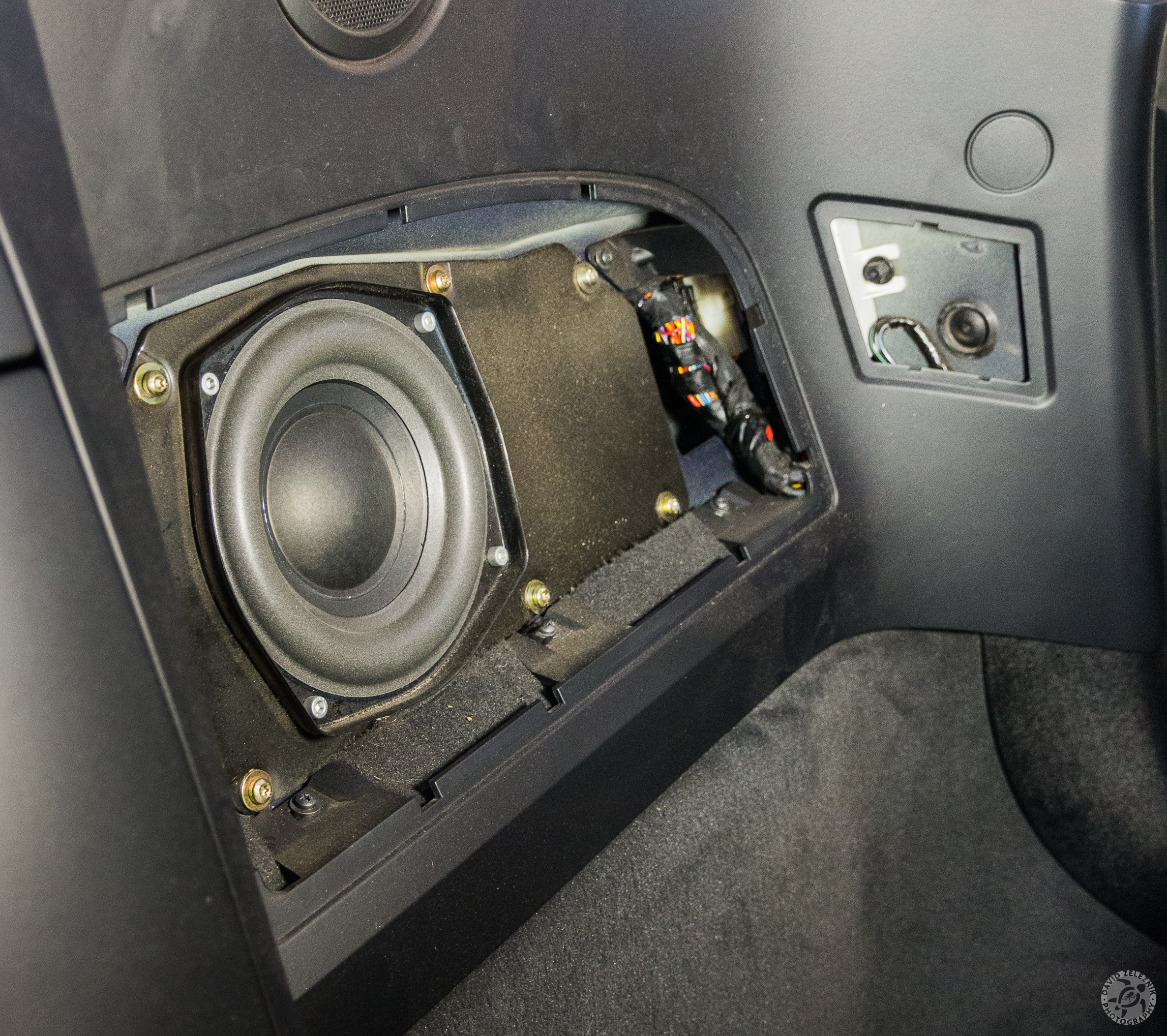
2 First step is to move the driver's seat as forward as possible, then use a nylon non-marring trim tool to unsnap the subwoofer grill and the small access panel to its right. The small white box visible through the access panel is the controller for the convertible top.
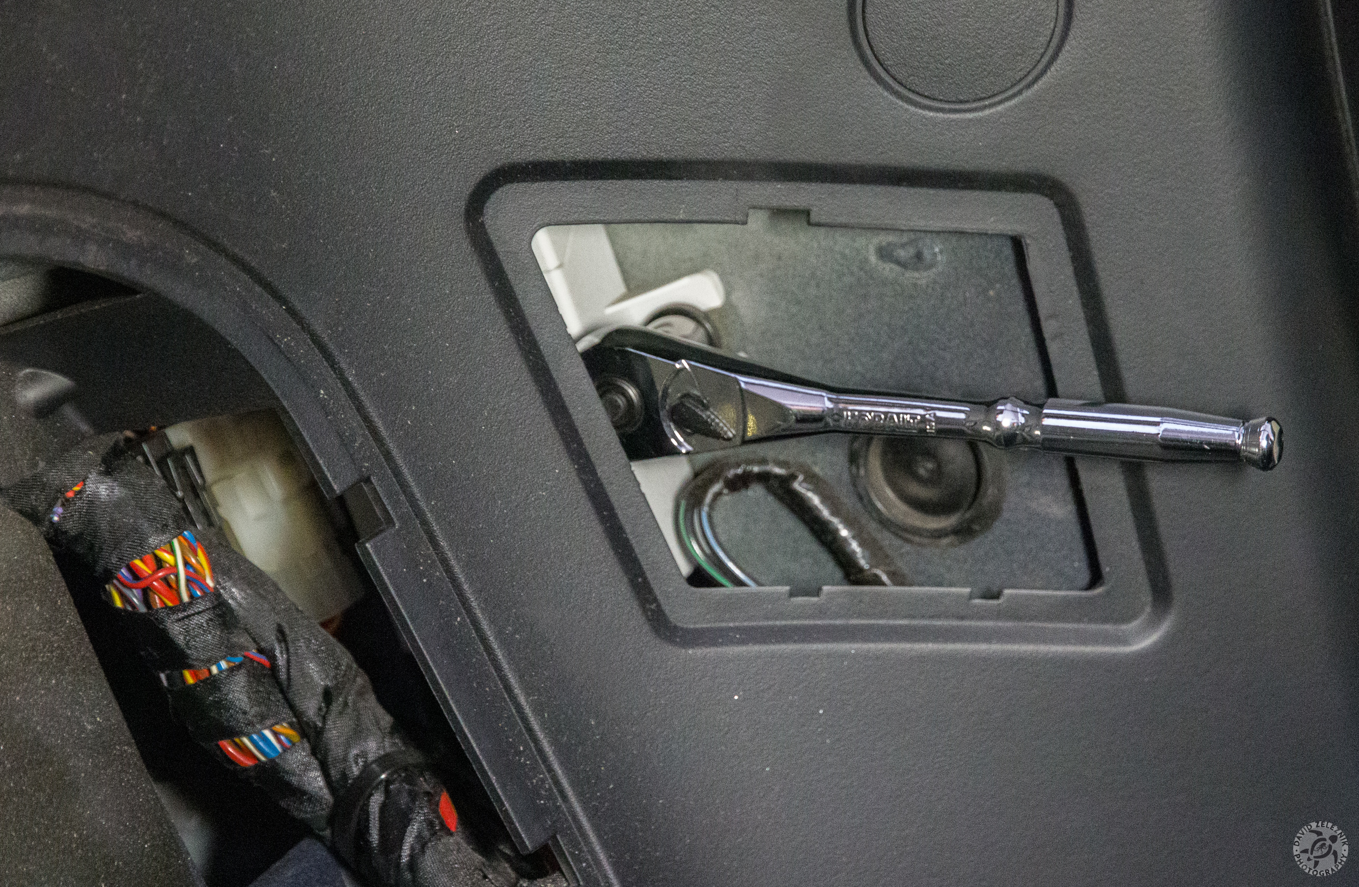
3 The top controller is held in place with a 10mm nut that you need to unfasten.
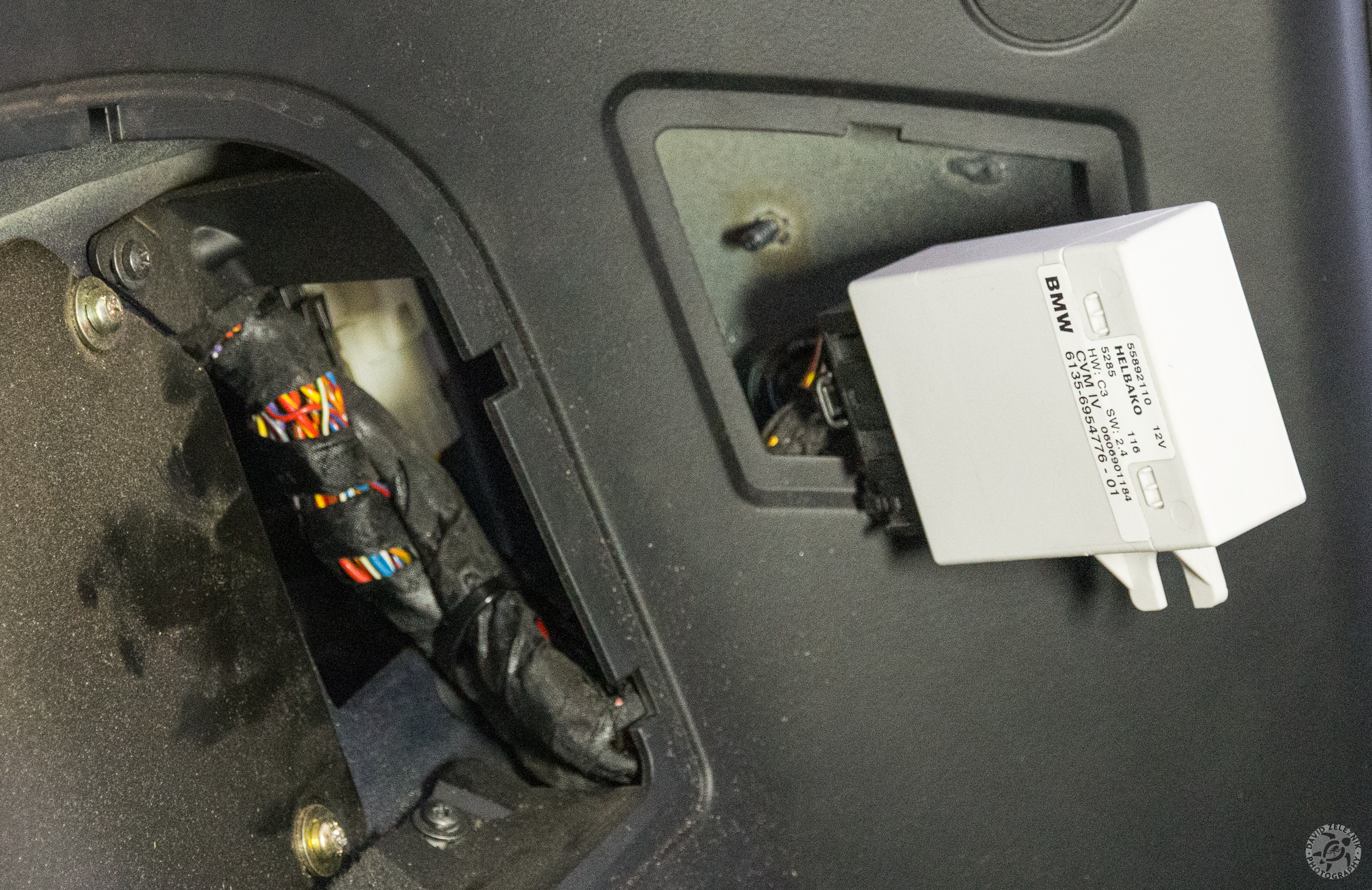
4 It takes a bit of finagling and manipulation of the stiff cables, but you should be able to pull the controller out through the panel opening.
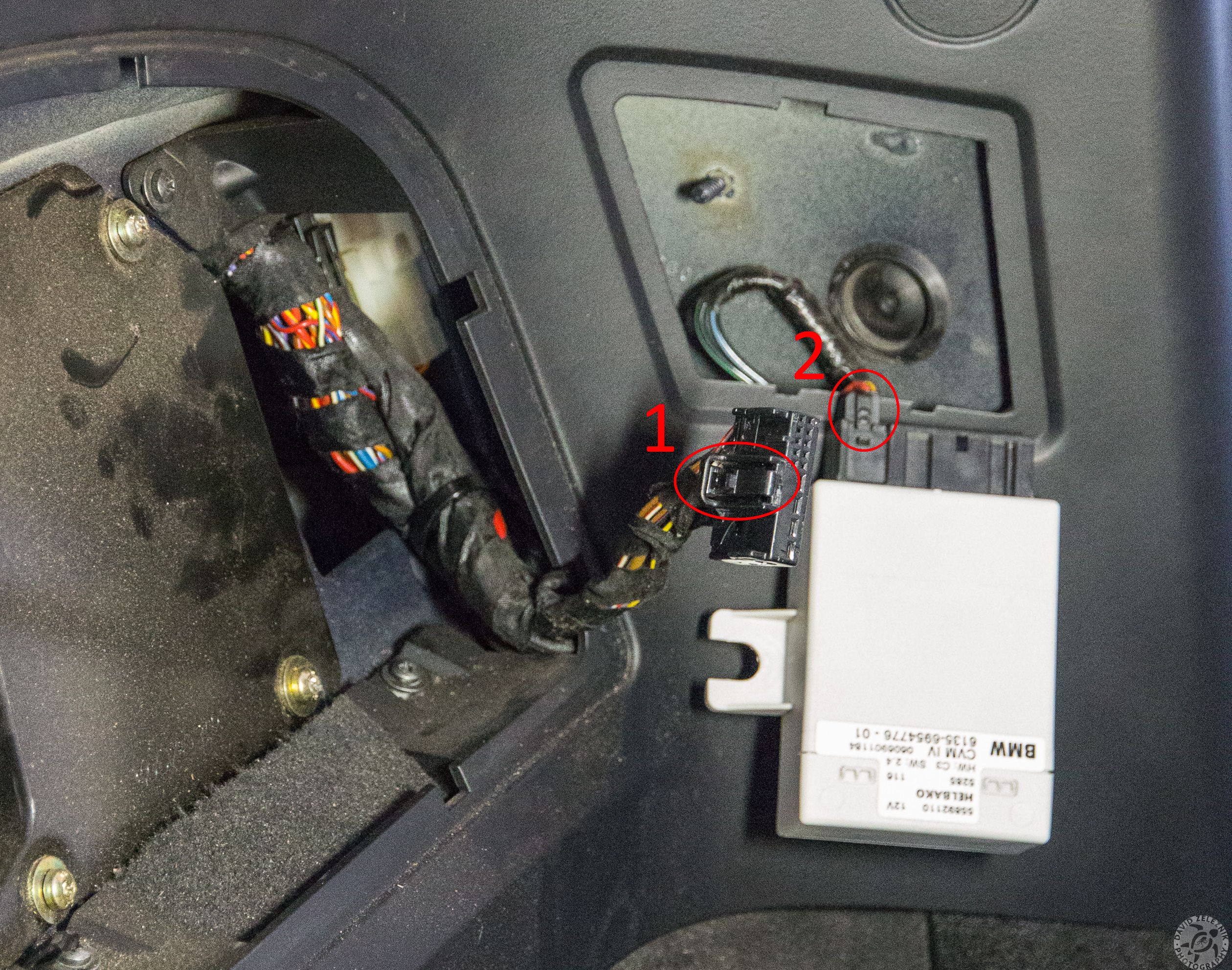
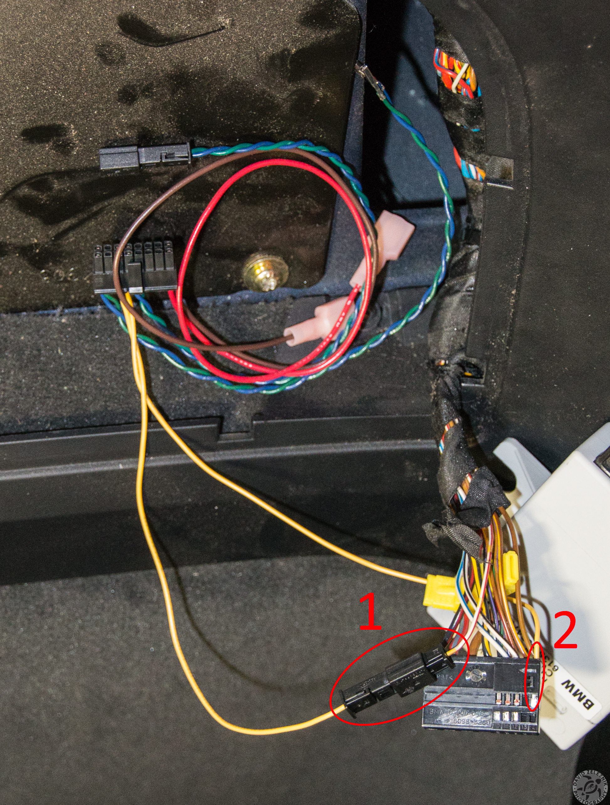
5 Disconnect the large plug from the top controller by pressing the locking tab (1). Leave the smaller connect (2) attached to the controller.
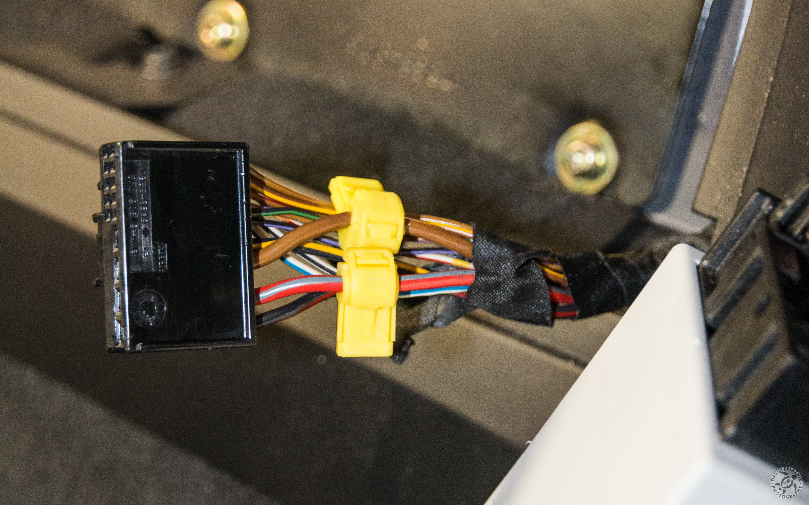
6 Thread the wire harness to exit from the subwoofer access panel, then peel back some of the tape to provide access to the bundled wires. Attach one of the t-tap connectors to the thick brown ground wire, and the other t-tap connector to the thick red/grey striped power wire.
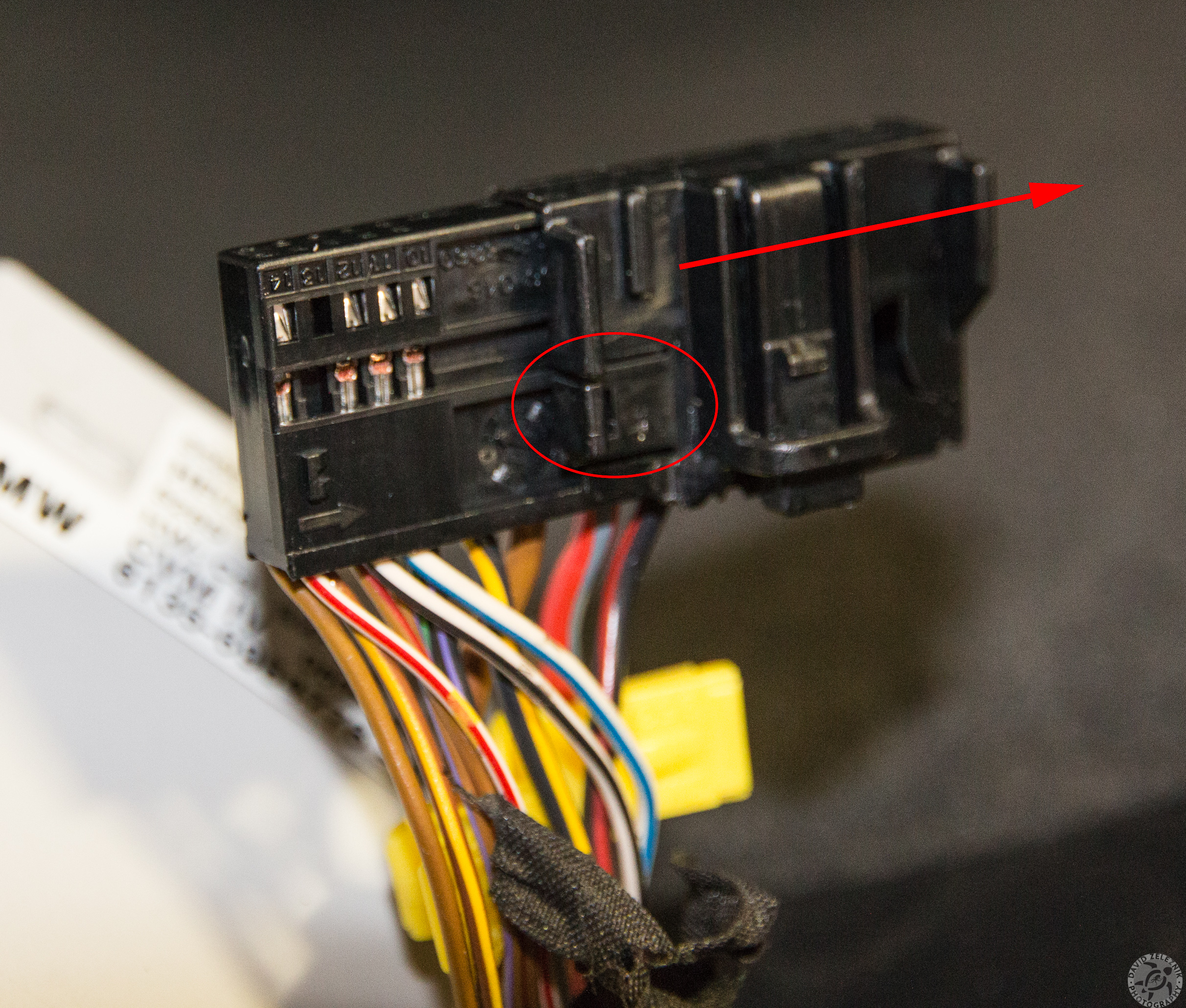
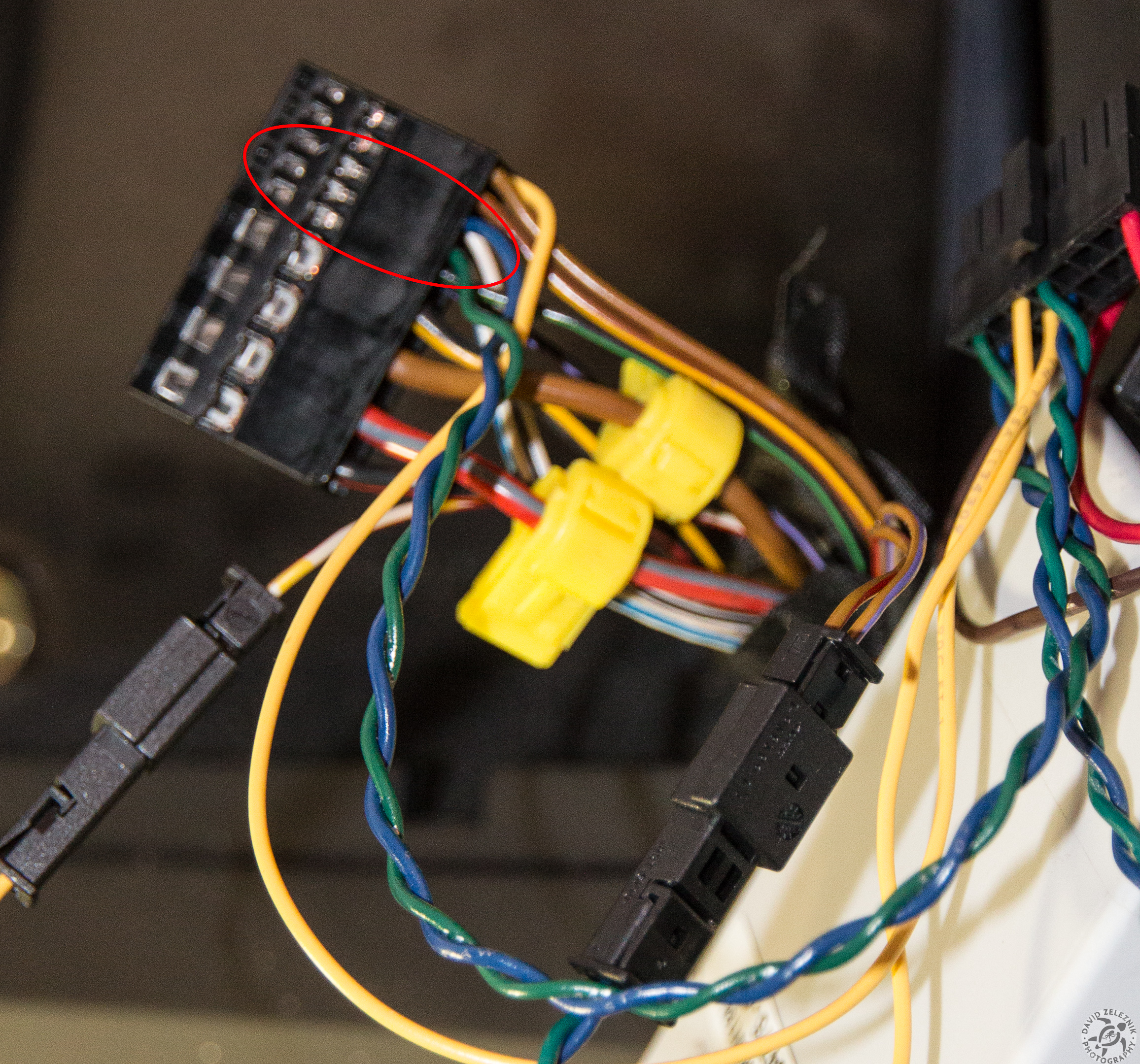
7 Now remove the connector from its outer shell. Lift and release the circled locking tab while sliding the shell off the connector.
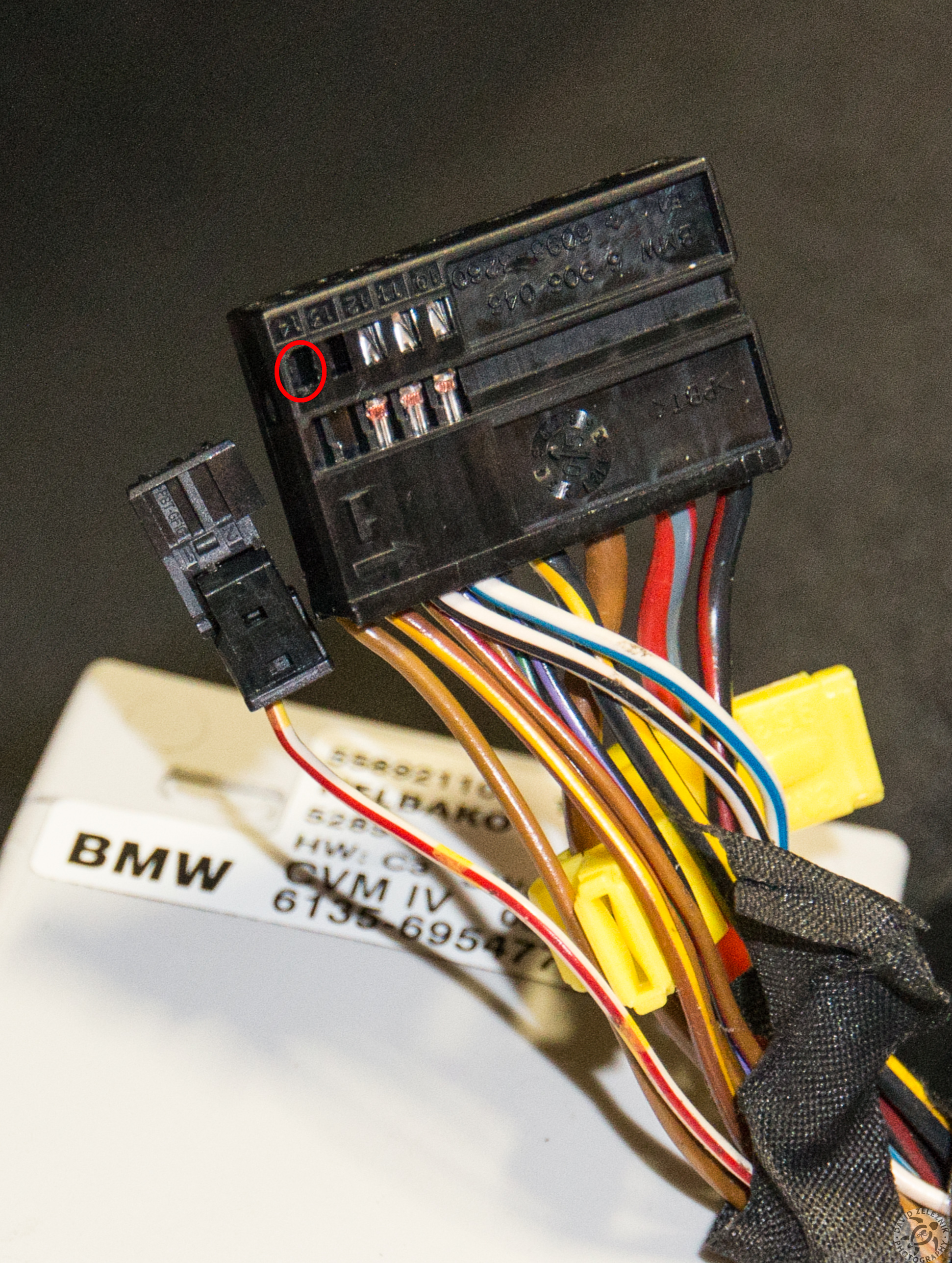
8 Next we need to remove the red/white striped wire from position #14 in the large connector. Do this by depressing the contact's locking tab through the circled window with a jeweler's screwdriver while pulling the wire. Then insert the red/striped wire's contact into position #1 of the small connector that came with the smartTop controller. Press down hard on the locking latch of the small connector to fully close it.
9 1) Plug the small connector that you just attached to the red/white striped wire into the matching connector on the wiring harness that came with the smartTop controller. Make sure that the red/white striped wire is in the same position and makes electrical contact with the yellow wire from the harness. 2) Take the other yellow wire from the smartTop controller harness and insert its contact fully into position #14 of the large connector.
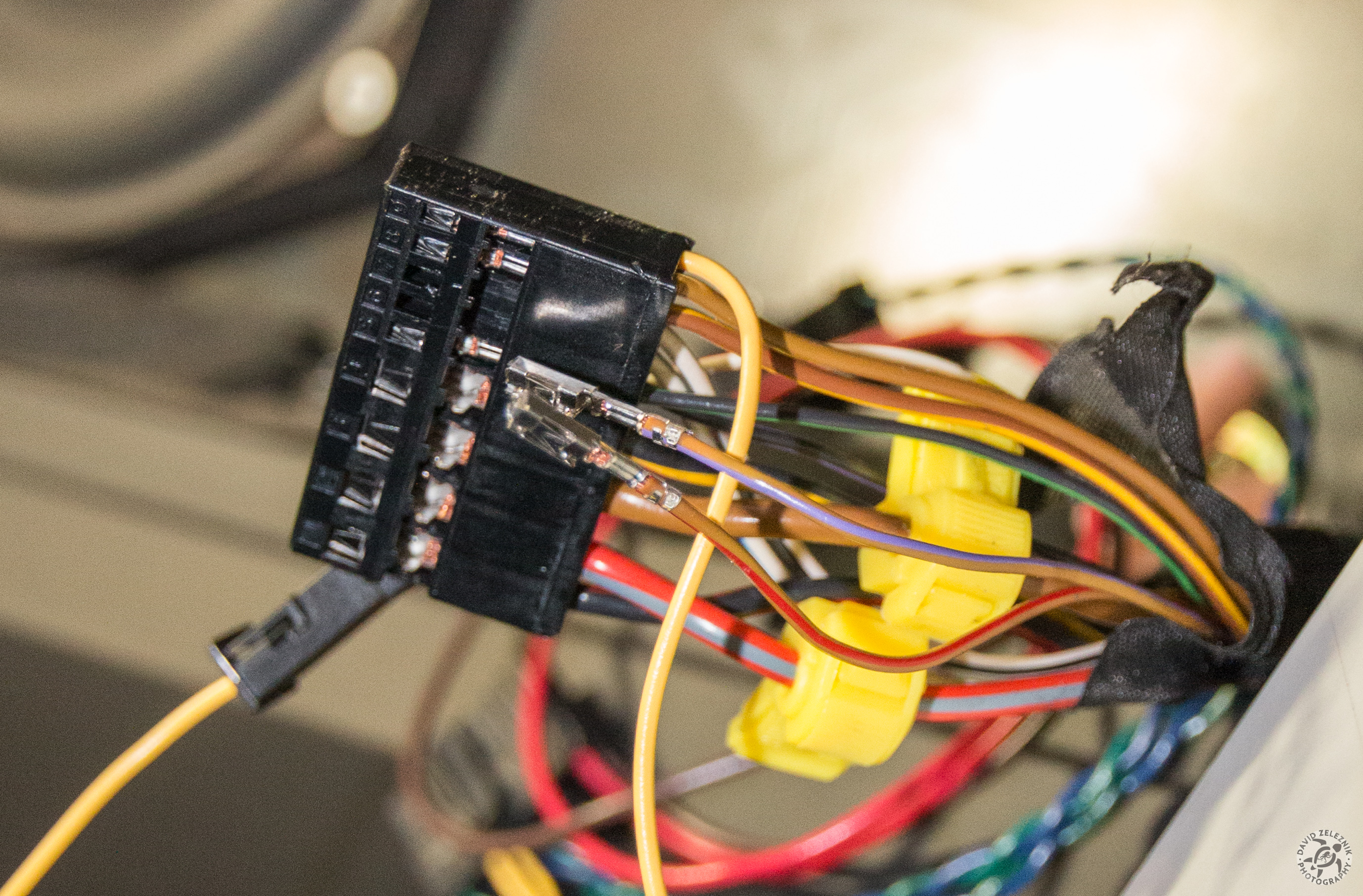
10 Remove the purple/brown striped wire from position #6 of the large connector, and the red/brown striped wire from position #7. Release the locking tab on the contacts the same way you did for the red/white striped wire.
11 Insert the purple/brown striped wire's contact into position #1 of the second small connector that was supplied with the smartTop controller. Insert the red/brown striped wire's contact into position #2. Then fully close the connector's locking latch and mate it with the connector attached to the green/blue twisted pair.
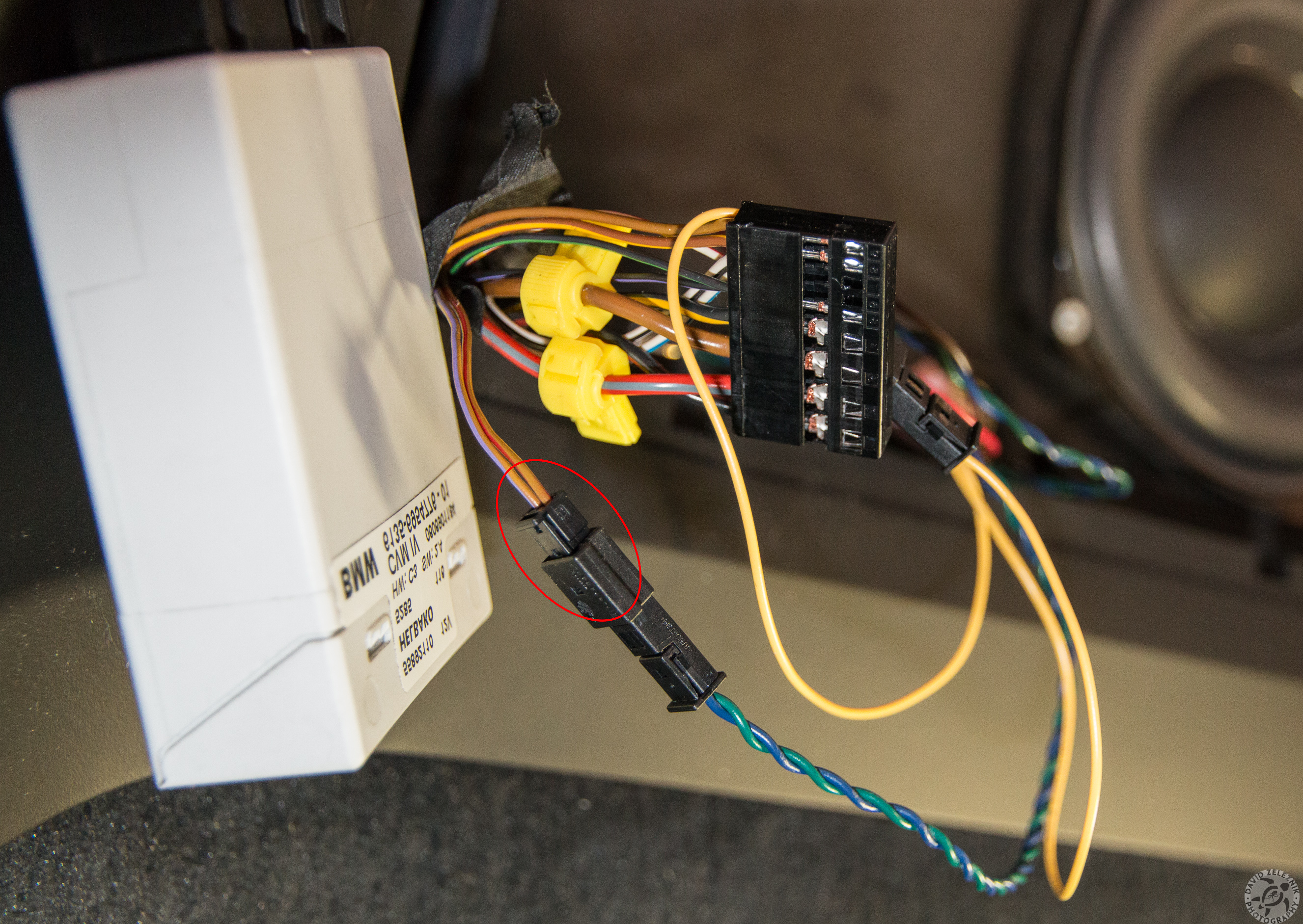
12 Insert the green wire's contact into position #6 of the large connector, and insert the blue wire's contact into position #7.
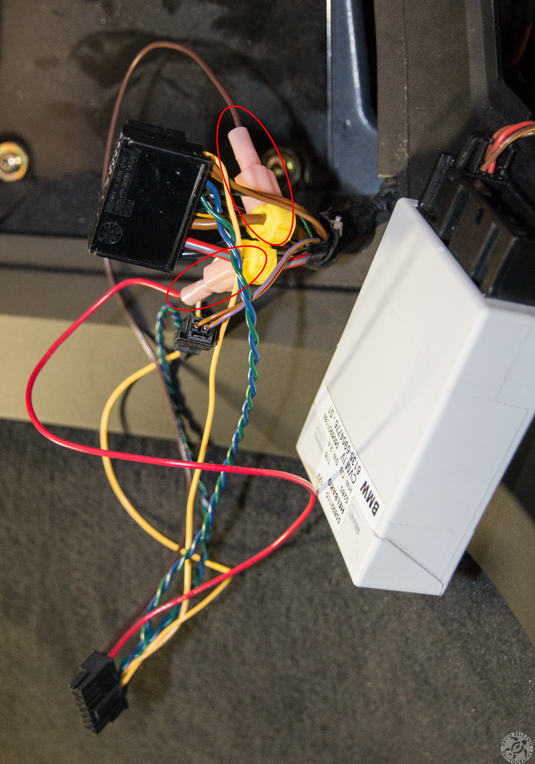
13 Plug the spade connector attached to the brown/ground wire of the smartTop harness into the t-tap connector attached to the brown/ground wire. Then plug the spade connector attached to the red/power wire of the smartTop harness into the t-tap connector attached to the red/grey striped wire.
14 Now, thread the large connector and it's harness back through the small access panel and plug it back into the convertible top controller.
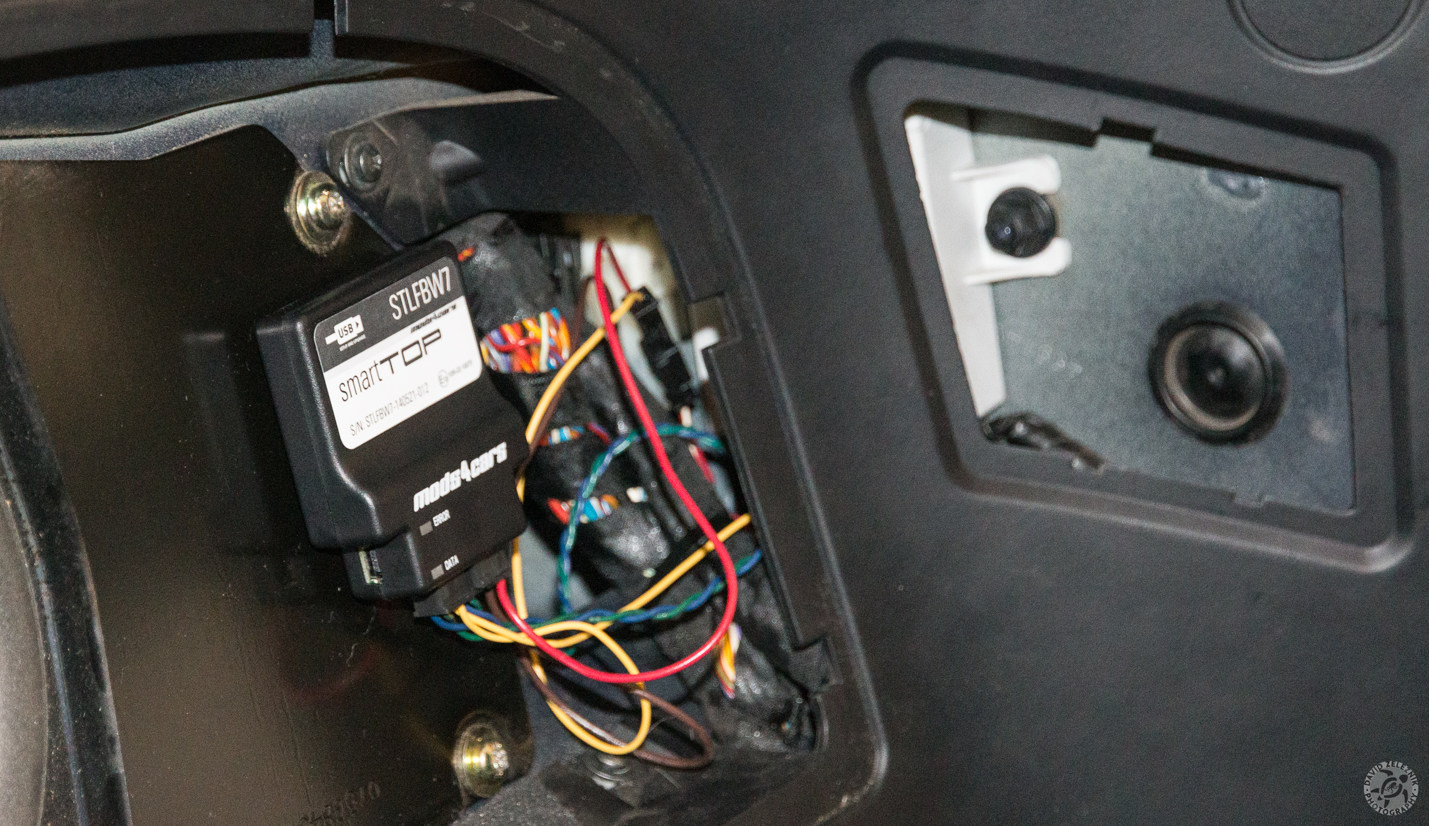
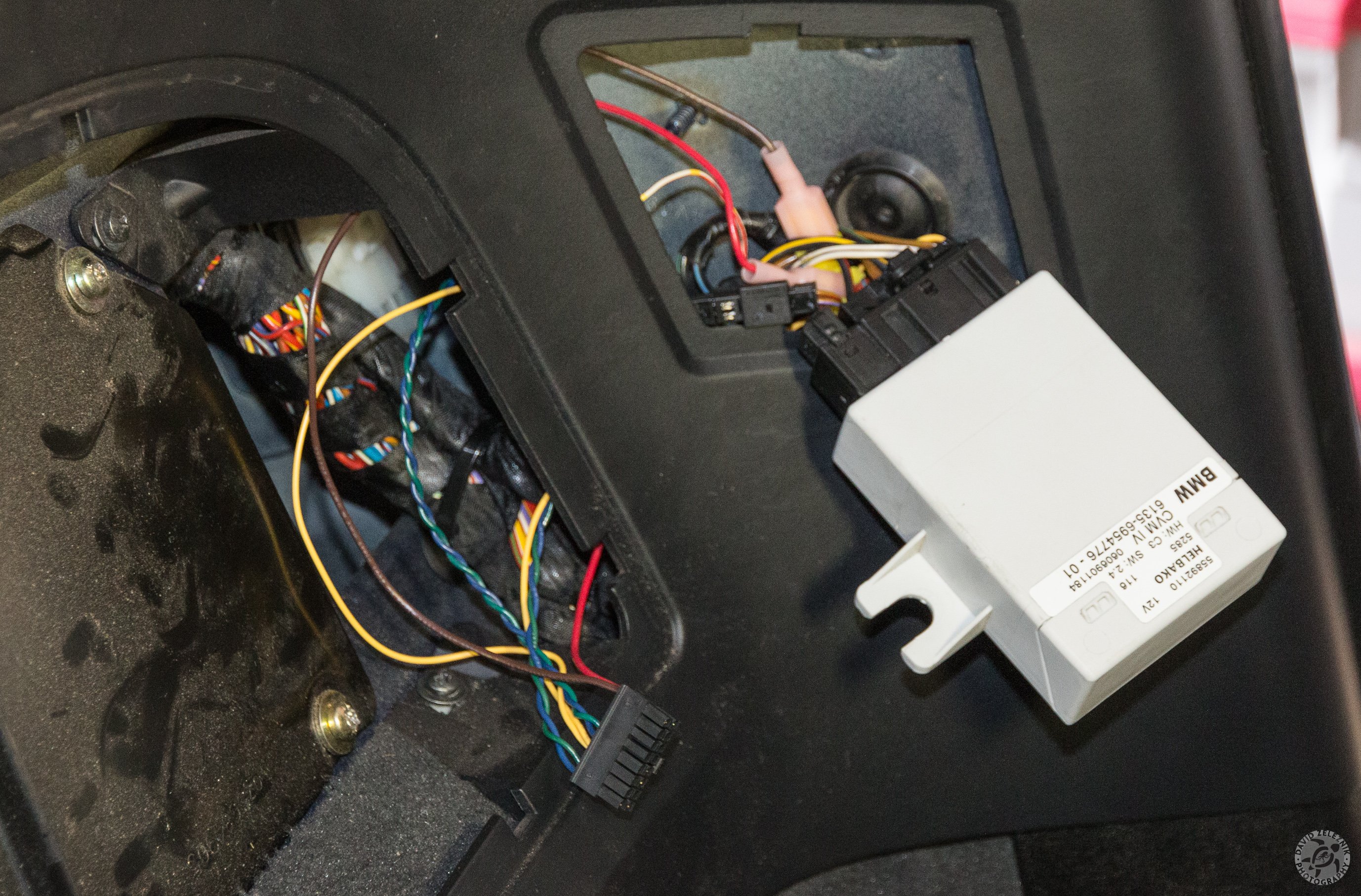
15 It takes quite a bit of jiggling and wiggling to get the convertible top controller back into place and fastened down with the 10mm nut. Then plug the harness into the smartTop controller and attach it to the subwoofer panel using the self-adhesive velcro square. Now it's time to follow the supplied installation and programming instructions to verify everything is working and reattach the access panel covers.